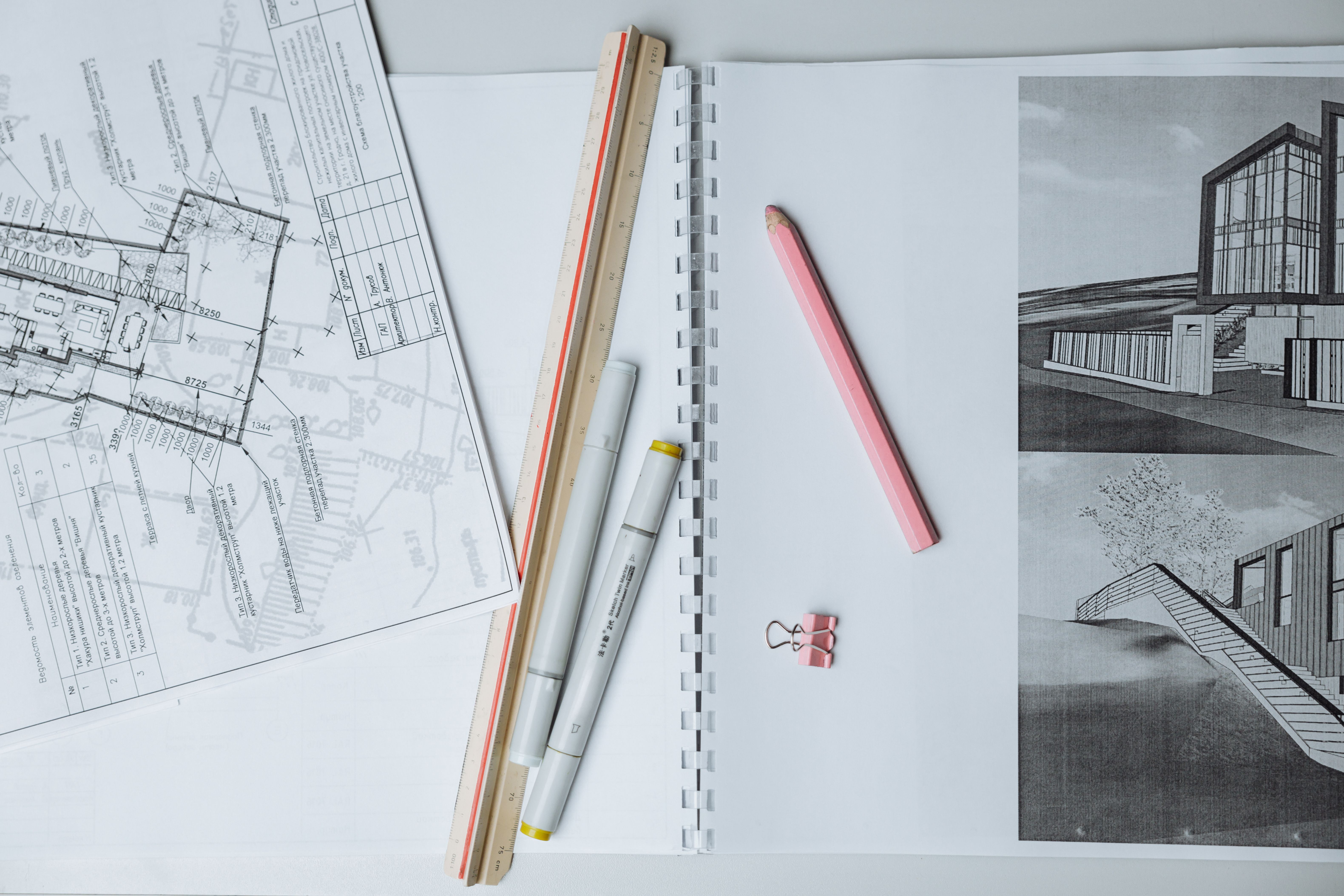
Translating engineering drawings is rarely a simple text replacement exercise. Anyone who has opened a localized DWG or DXF file only to find non-standard symbols rendered as mystery rectangles, translated text overlapping critical dimensional lines, or missing layers knows how fragile technical files can be. In global manufacturing, aerospace, and civil engineering, a single misread tolerance or corrupted callout on an assembly sheet can halt a production line or result in expensive material scrap.
Navigating these challenges requires bridging two distinct disciplines: precise engineering literacy and specialized Desktop Publishing (DTP) for computer-aided design systems.
Technical Hurdles in CAD Drawing Localization
Engineering files rely on structural layers, vector lines, geometric dimensioning and tolerancing (GD&T) callouts, and specialized vector typography. When these documents cross international borders, three primary mechanical issues tend to emerge.
Text Expansion and Visual Overlap
German, Spanish, and Russian translations often expand text length by 20% to 35% compared to English originals, while Asian scripts like Chinese or Japanese compress multi-word terms into dense logograms. Standard translation management systems (TMS) typically treat CAD callouts as plain text strings, ignoring the physical spatial boundaries of the drawing frame. When longer translated strings are imported back into standard CAD environments without dynamic scaling, they frequently collide with projection vectors, section cutouts, and title block borders.
Font Incompatibility and Special Symbol Corruption
CAD software relies heavily on compiled vector fonts (.shx) alongside system TrueType (.ttf) fonts to render standard drafting annotations. Specialized symbols—such as roughness marks, surface texture indicators, weld symbols, and degree signs—are mapped to specific font tables. Extracting text for translation without preserving file-specific font packages causes character mapping failure, turning vital symbols into question marks or blank blocks (? or □).
Layer Integrity and Vector Asset Preservation
Complex mechanical blueprints separate dimensions, notes, mechanical outlines, and spatial grids across distinct drawing layers. Translating directly over the original source graphics without strict layer management hazards locking or merging operational layers, rendering the final engineering draft uneditable for downstream structural engineers.
Accuracy Risks in Mechanical Annotations and GD&T Standards
Beyond spatial typography, the linguistic accuracy of shorthand engineering annotations directly impacts manufacturing outcomes. Engineering drawings use standardized international nomenclature that varies significantly across industrial jurisdictions.
GD&T and Symbol Standards: International Organization for Standardization (ISO) and American Society of Mechanical Engineers (ASME) standards handle geometric controls differently. For example, ISO 1101 and ASME Y14.5 define positional tolerances and datum references using distinct symbol frameworks. Misinterpreting these shorthand annotations during translation risks changing the mechanical intent of a part.
Material Designations and Abbreviations: Technical callouts frequently feature shortened material codes such as SUS304 (stainless steel), Q235, or AISI 4140, along with processing instructions like T6 heat treatment, passivation, or anodization. Translating these abbreviations literally rather than mapping them to destination-market equivalents (e.g., DIN standards in Germany or JIS standards in Japan) leads to incorrect raw material procurement.
Industry audits across global manufacturing supply chains repeatedly show that technical documentation defects contribute significantly to engineering change orders (ECOs). Ensuring that localized drawing packages maintain strict dimensional alignment and exact material equivalence reduces expensive rework during early-stage prototyping.
Integrating Mechanical Literacy with Professional CAD DTP
Overcoming these technical hurdles requires an integrated workflow that couples bilingual mechanical engineers with dedicated CAD DTP operators. A robust CAD localization process relies on a four-step technical methodology:
Pre-Translation Extraction: Extracting translatable text strings while isolating embedded blocks, dynamic attributes, and dimension locks to maintain original drawing coordinates.
Terminology Alignment: Mapping all GD&T symbols, material grades, and shorthand callouts against industry-approved glossaries.
Post-Translation Layout Adjustment: Re-engaging CAD specialists to manually adjust text box boundaries, lead line placements, font size scaling, and line-wrap rules within target layers.
Visual Engineering QA: Verifying the localized draft against the source file side-by-side to guarantee that no vector lines, centerpoints, or tolerances were altered.
Seamless Technical Localization Solutions
Maintaining engineering precision across global manufacturing projects demands a technical partner capable of handling intricate CAD workflows without sacrificing linguistic rigor. Artlangs Translation delivers end-to-end language and technical solutions backed by more than 20 years of global service experience. Supported by a network of over 20,000 professional linguists and subject-matter experts, the organization provides accurate translation and localization across more than 230 languages.
Beyond complex CAD engineering drawing translation and specialized DTP layout, the company's capabilities cover multimedia localization, short drama subtitle localization, game localization, multi-language voiceover for short dramas and audiobooks, as well as multi-language data annotation and transcription services. With a long track record of successfully executed enterprise projects worldwide, complex technical documents are systematically processed, formatted, and delivered to meet stringent global industry standards.